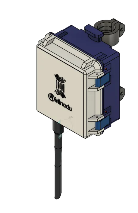
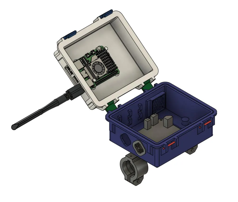
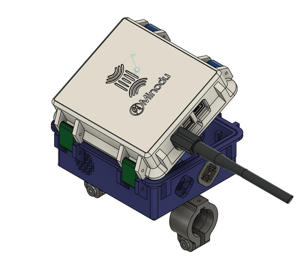
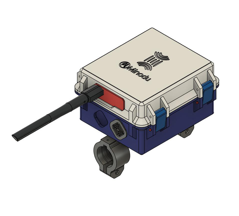
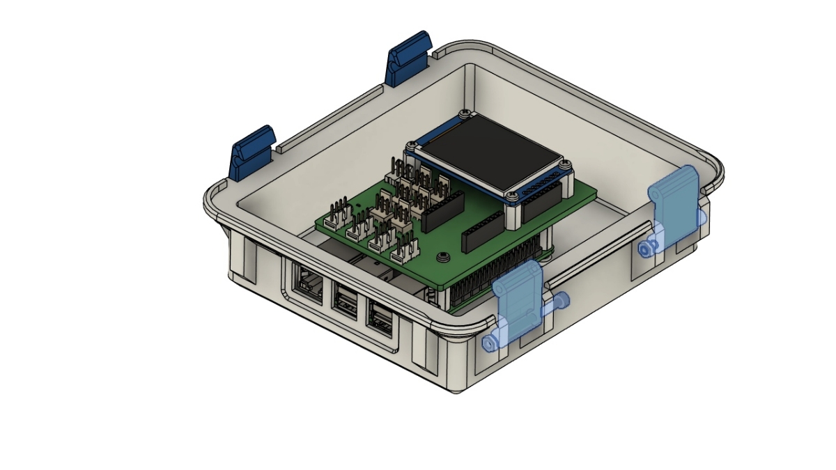
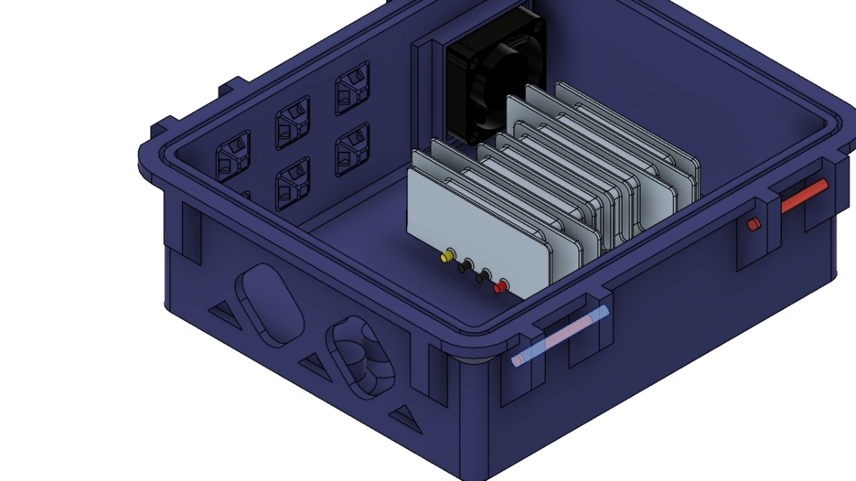
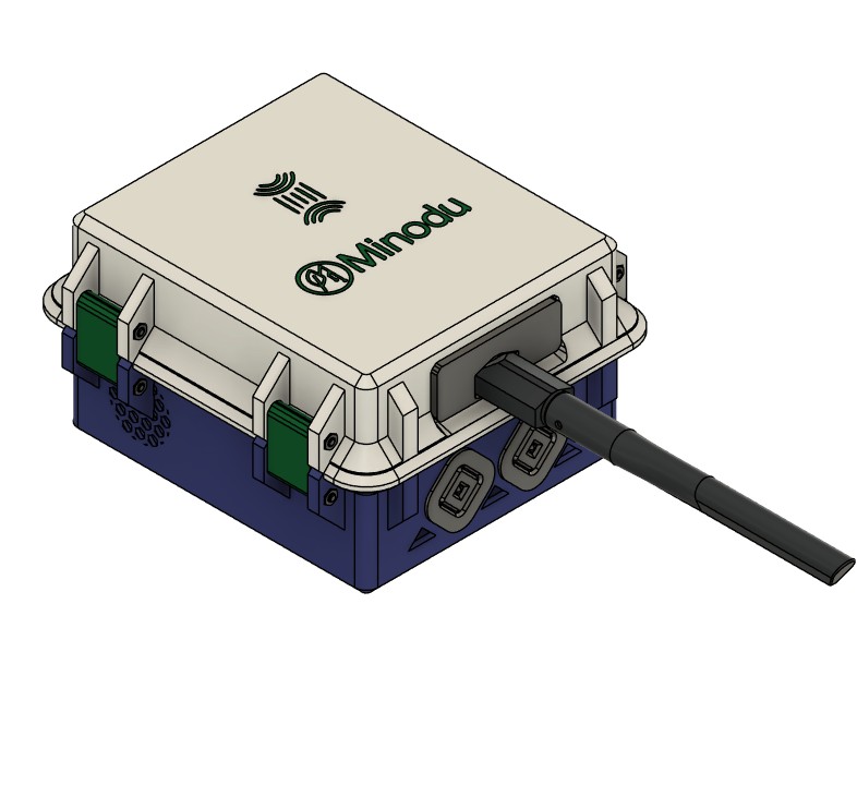
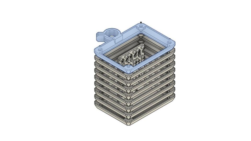
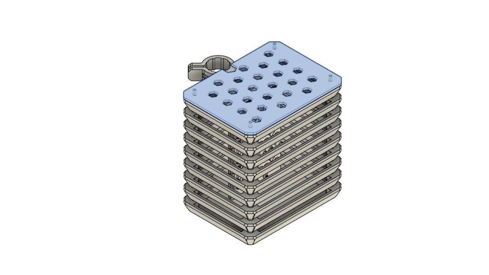
The Minodu Local Community Network mainly consists of two parts: the Local Community Network: a Raspberry Pi, the TeleAgriculture Board and a power converter, housed in a custom 3D-printed protection box; and the 3D-printed Stevenson Screen in which the environmental sensors are fixed and protected.
Idealy PETG, ASA, ABS ( Unprotected ABS should almost never be used outdoors. To make ABS suitable for the sun, it must be coated in a UV-resistant paint or clear coat)
3D printers only understand G-code language (geometric code); So what we need to do is to convert the STL files into G CODE.
Recommended tool: I personally use OrcaSlicer but they all work the same.
Tool tutorial: Watch this quick video to get you started if you are new to 3D printing with OrcaSlicer.
Here is The Orca slicer projectfile withh all the parts
- Minodu_Box.3mf
Protection Box assembly
This guide explains how to assemble the 3D-printed protection box for the Minodu Local Network. The enclosure is designed to house a Raspberry Pi 5, the Tele-Agriculture Board, a 12V-to-5V DC-DC power converter, sensor cables, and can be mounted on a pole for outdoor installations with a Stevenson screen.
Assembly video
Required Components
3D Printed Parts
Top cover
Bottom enclosure
2 × Hinges
2 × Latches
TPU dust cap
Electronics
Raspberry Pi 5
Raspberry Pi Active Cooler
Tele-Agriculture Board
12 V → 5 V DC-DC Converter
30 × 30 × 10 mm cooling fan
Hardware
04x M2.5 heat-set inserts
04x M2.5 × 20 mm standoffs
04x M2.5 × 6 mm screws
06x M3 × 30 mm hex socket head screws
06x M3 hex nuts
02x M6 heat-set inserts
02x M6 × 14 mm countersunk screw
Step by step assembly
Step 1 – Install Raspberry Pi Inserts
Steps
Images
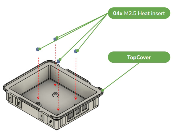
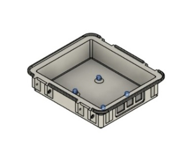
Turn the top cover upside down. Insert the M2.5 heat-set inserts into the designated mounting holes using a soldering iron or heat-set insert tool.
Ensure every insert sits perfectly flush with the plastic surface. CAUTION: Allow the inserts to cool before continuing.
Step 2 – Mount the Raspberry Pi
Steps
Images
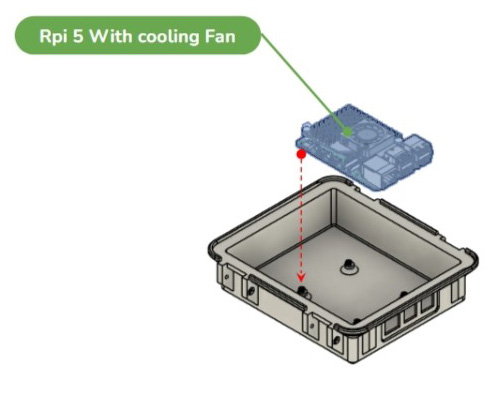
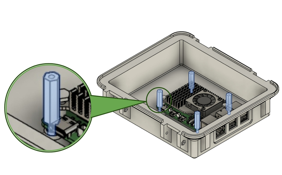
Position the Raspberry Pi 5 (with its cooling fan already installed) over the inserts.
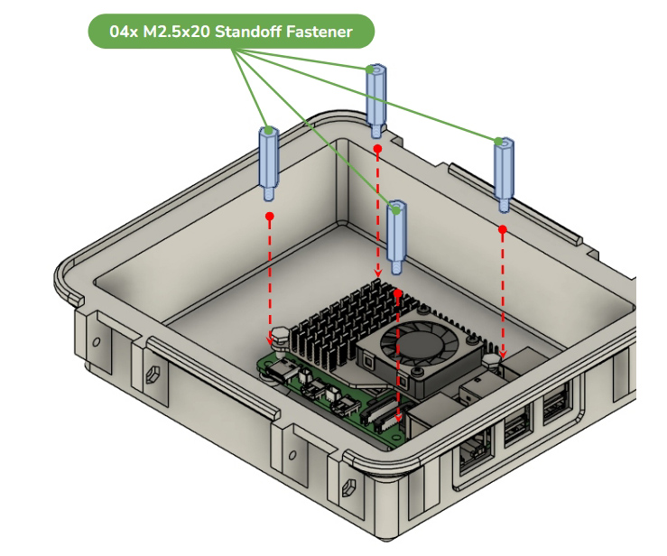
Install the 20 mm M2.5 standoffs and secure the Raspberry Pi.
Verify that the board is firmly mounted.
Step 3 – Install the Tele-Agriculture Board
Steps
Images
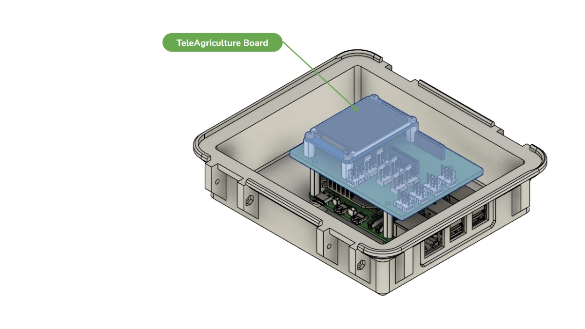
Place the Tele-Agriculture Board on top of the standoffs.
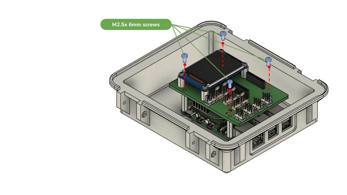
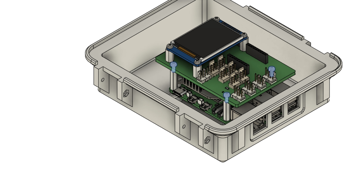
Secure it using M2.5 × 6 mm screws.
Install the fourth screw located beneath the display. IMPORTANT: Check that nothing moves or is loose.
Step 4 – Assemble the Latches
Steps
Images
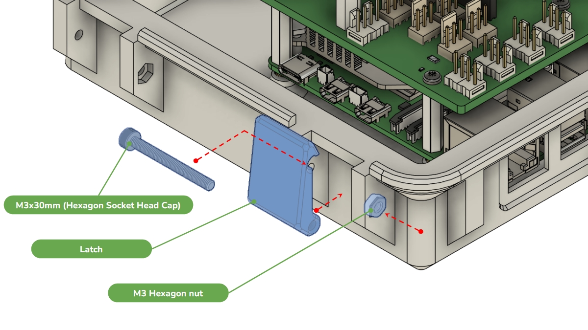
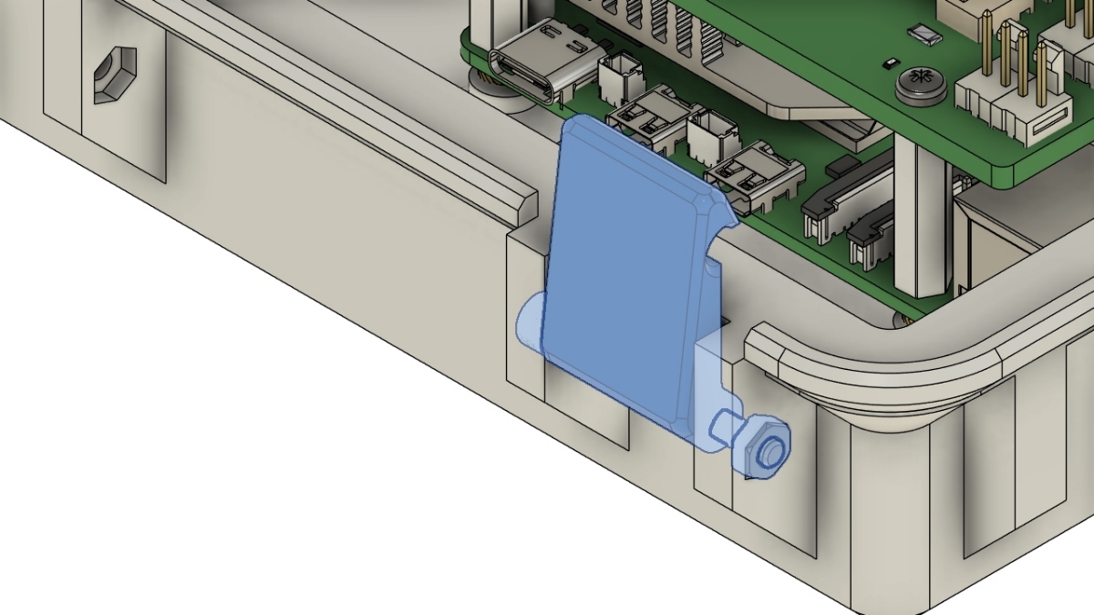
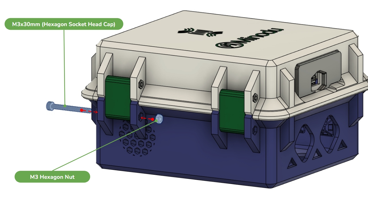
Insert one M3 hex nut. Align the latch. Insert one M3 × 30 mm screw.
Tighten until secure.
Repeat for the second latch.
Step 5 – Assemble the Hinges
Steps
Images
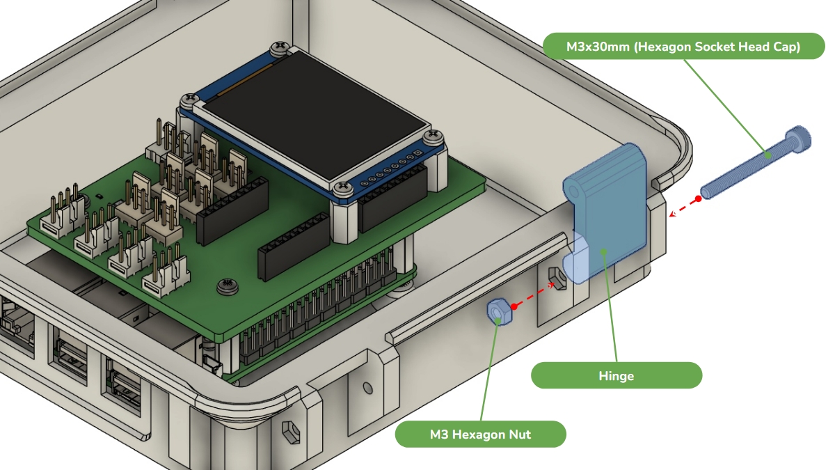
On the other side of the box, using the same hardware: Insert the M3 nut. Align the hinge. Insert the M3 × 30 mm screw. Tighten.
Repeat for the second hinge. Ensure both hinges rotate freely.
Step 6 – Install the DC Converter Insert
Steps
Images
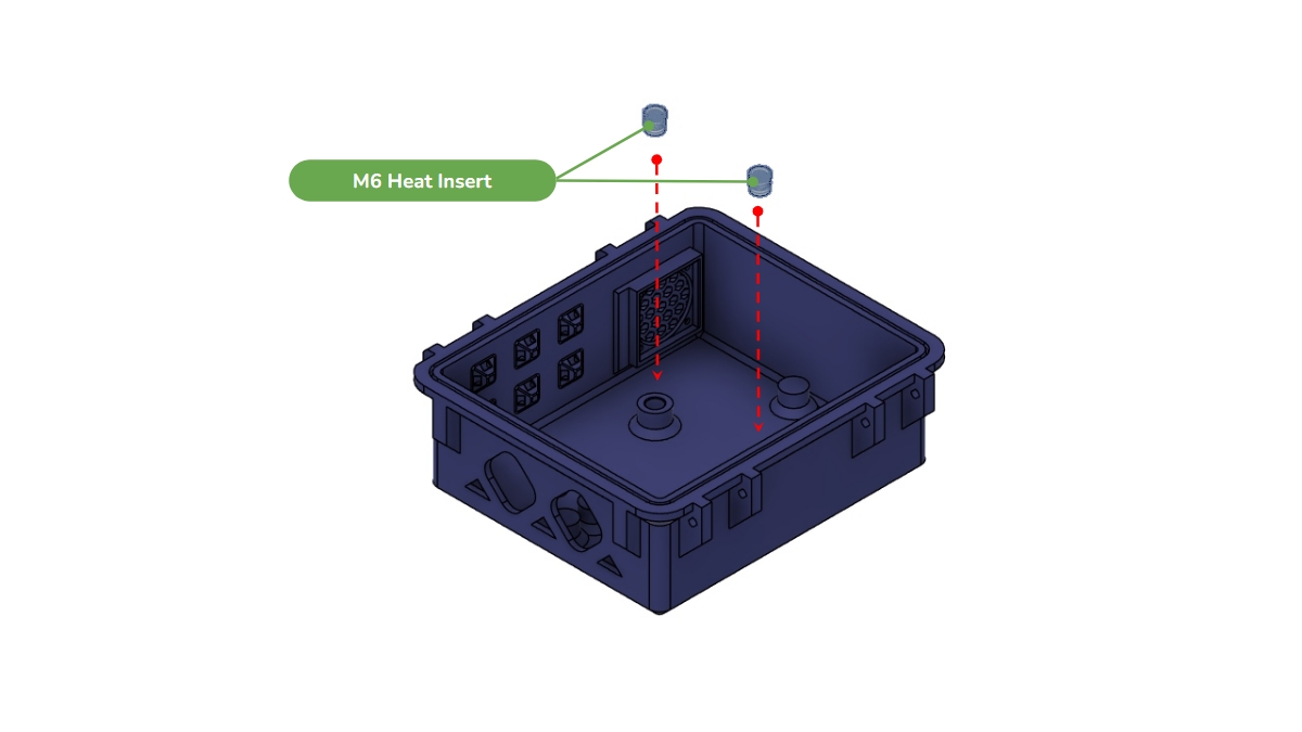
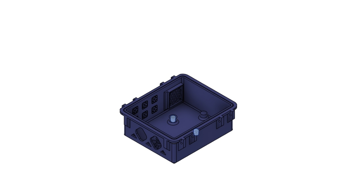
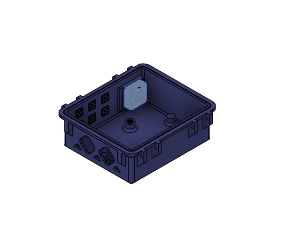
Install the M6 heat-set insert for the DC-DC converter into the bottom enclosure.
Make sure it is completely flush with the plastic.
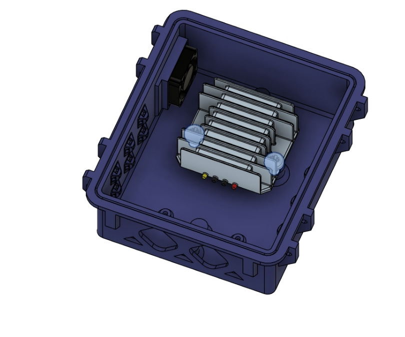
Step 7 – Install the Cooling Fan
Steps
Images
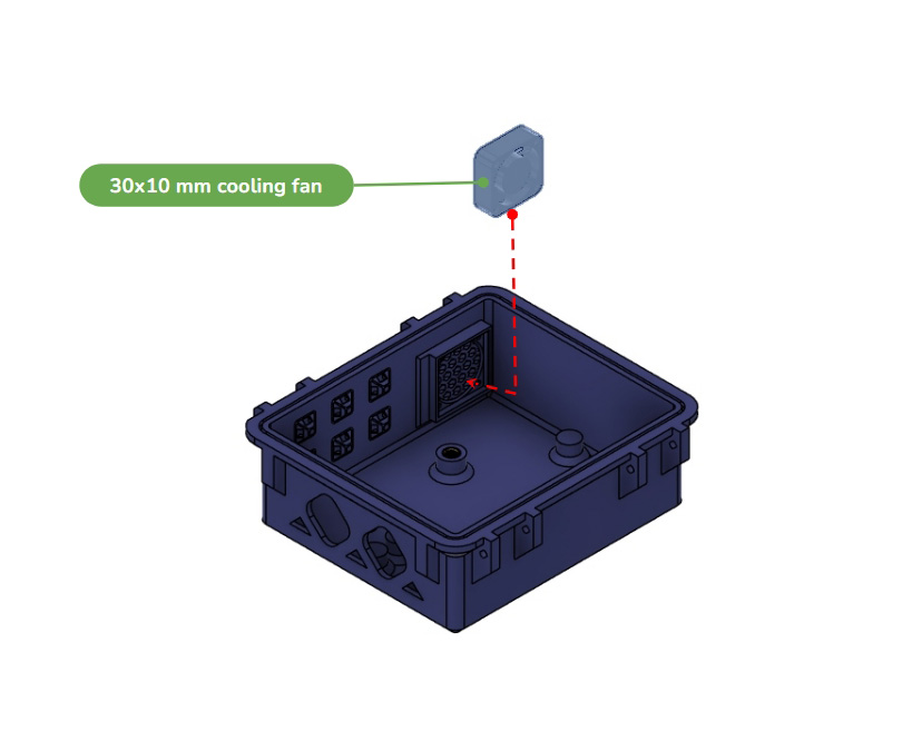
Insert the 30 × 30 × 10 mm cooling fan into its ventilation opening. IMPORTANT: The cable exits toward the wiring opening. Airflow is directed from inside the enclosure to the outside.
Push the fan fully into position. If necessary, secure it with a very small amount of glue. CAUTION: Ensure the fan blades rotate freely. If the blades touch the >enclosure, If they rub against the enclosure, it can be jammed, overheat and be fried.
Step 8 – Install the DC-DC Converter
Steps
Images
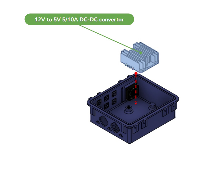
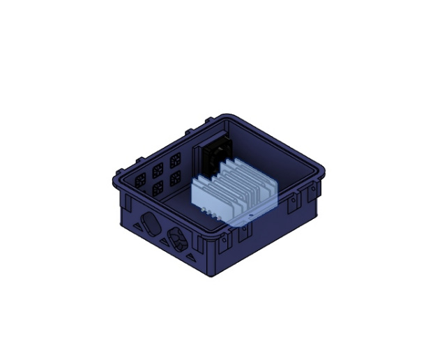
Position the 12V-to-5V converter inside the enclosure.
Align the mounting holes with the insert.
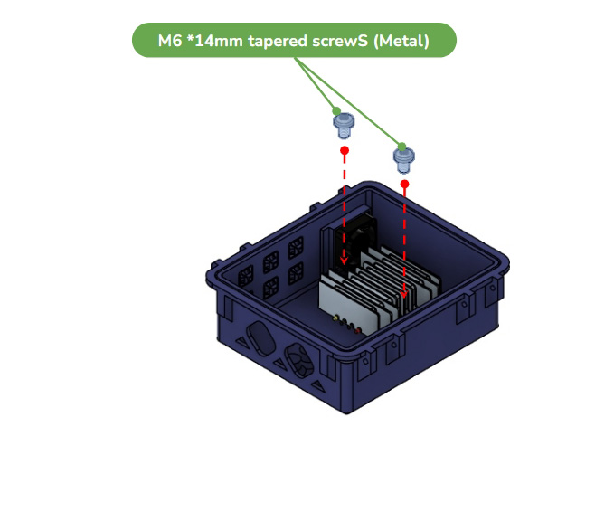
Secure it using the M6 × 14 mm countersunk screw.
Ensure the wiring faces the cable exit.
Step 9 – Join Both Halves
Steps
Images
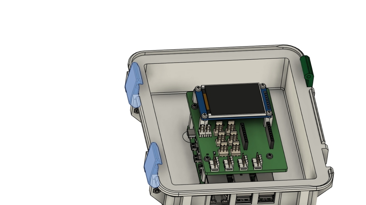
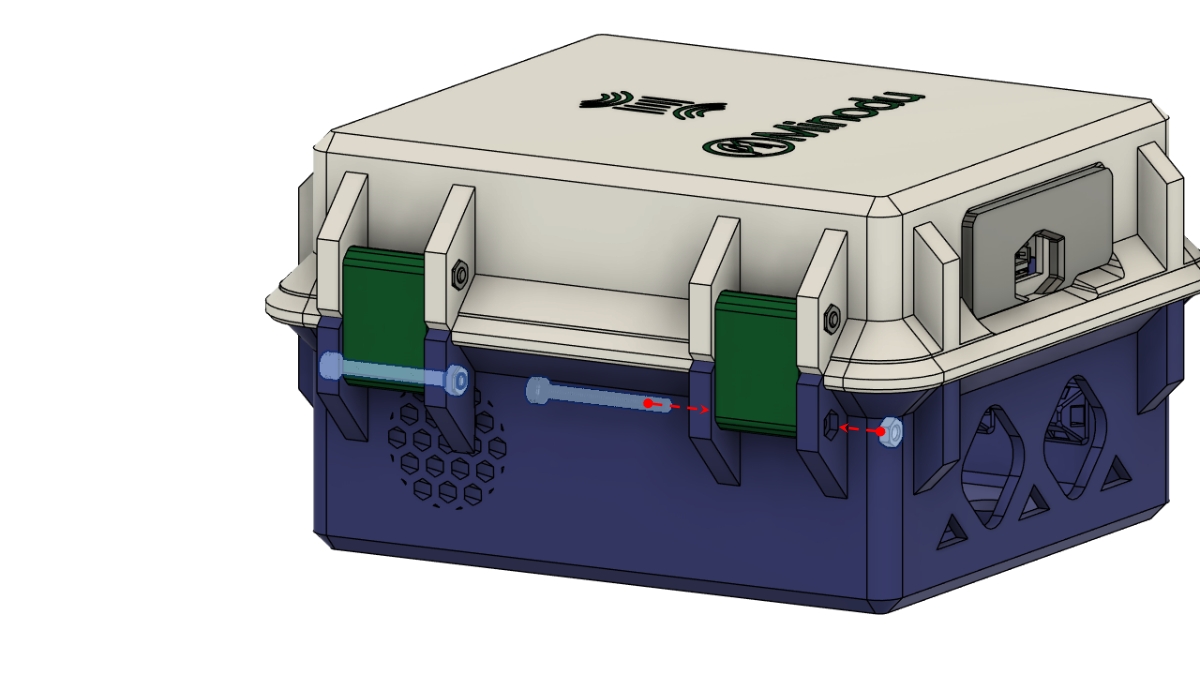
Align the hinge side first. Insert the hinge screws, nuts and, tighten.
Then align the latch side and secure it. Verify that: A) The enclosure opens smoothly. B) The enclosure closes correctly.
Step 10 – Install the Latch Clips
Steps
Images
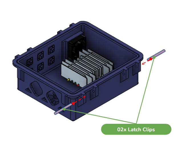
Insert the two printed latch clips into the lower enclosure. Push them fully into place until flush.
Close the enclosure and verify that the latches lock securely.
Step 11 – Final Assembly
Steps
Images
Install: A) TPU dust cap; B) Wi-Fi antenna; C) Sensor cables. Install the dust cap around the cables to maintain dust protection. Route all cables through the cable openings.
The enclosure is now ready to be mounted on a pole together with the Stevenson screen for outdoor deployment.
Stevenson Screen Assembly
This guide explains how to assemble the 3D-printed Stevenson Screen and install the environmental sensors.
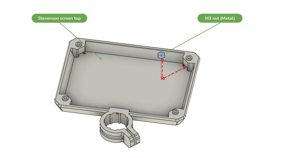
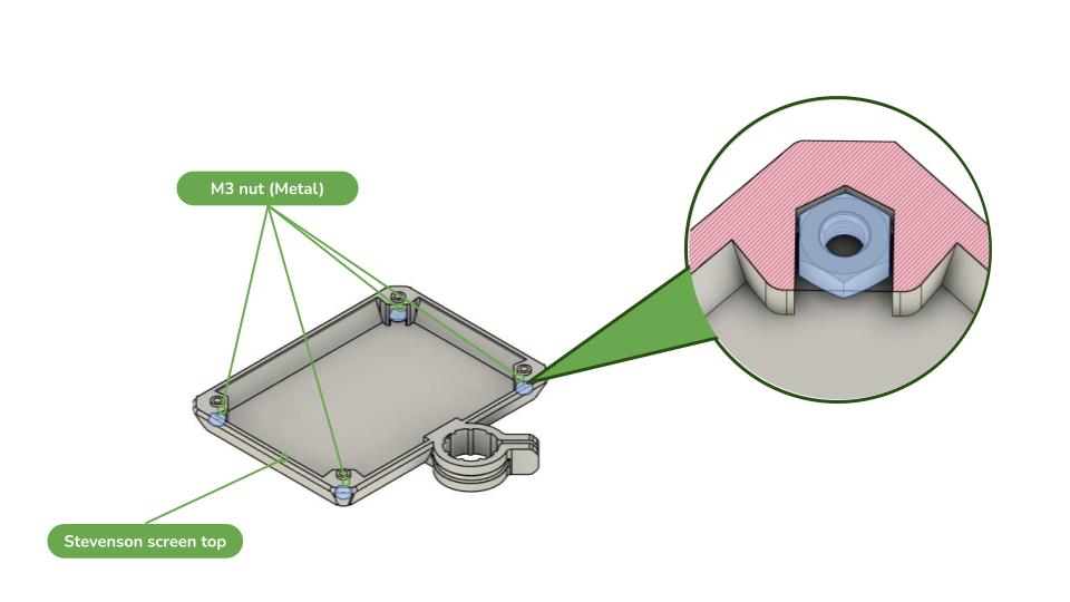
Take the Stevenson Screen top and locate the four recessed holes. Insert the four M3 nuts into the recessed holes.
Push each nut fully into its recess and make sure that they are properly seated and secure.
Step 2 – Install the Threaded Rods
Steps
Images
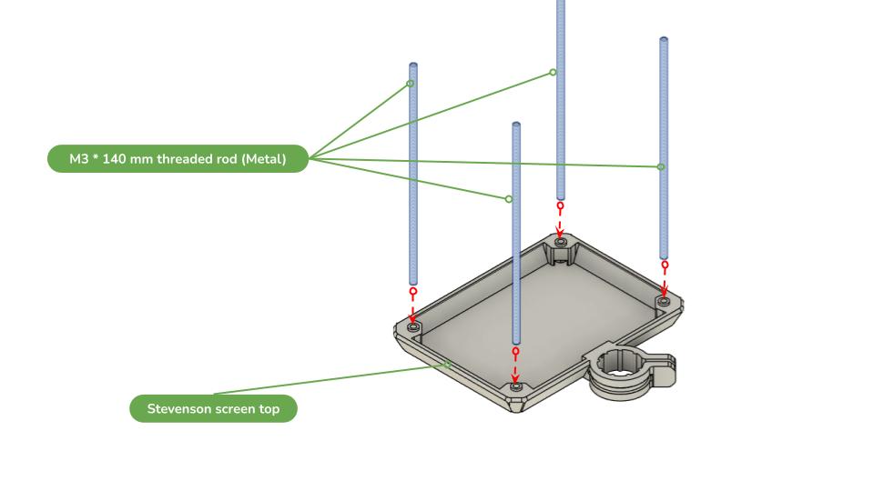
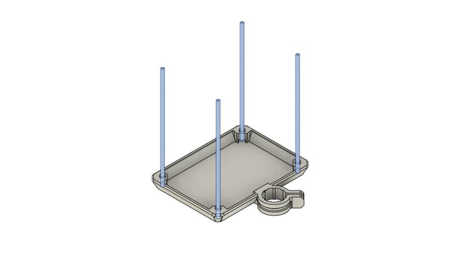
Take the four M3 × 140 mm threaded rods. Insert one threaded rod into each of the four holes and screw them gently into the M3 nuts installed in the previous step. Do not overtighten (⚠️ Important: Tighten the rods only enough to hold them securely. Excessive force may damage or crack the 3D-printed Stevenson Screen top).
Make sure all four rods are secure and properly aligned, then set the assembly aside.
Step 3 – Install the M2 Heat-Set Inserts in the Sensor Plate
Steps
Images
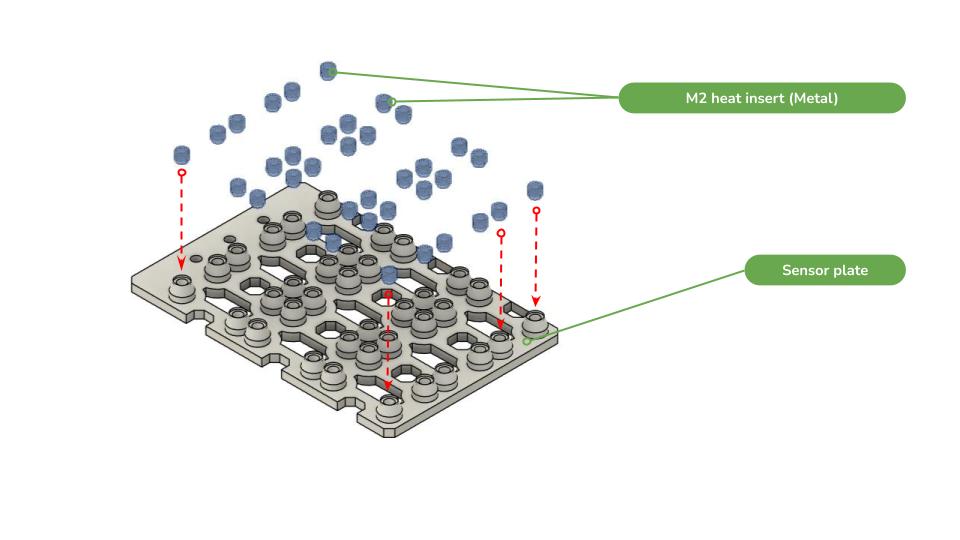
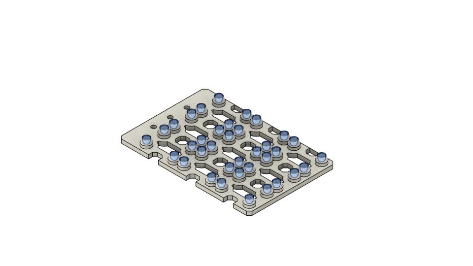
Take the sensor plate and install the M2 heat-set inserts into the designated mounting holes. The position of the inserts can be adapted according to the sensors being used.Ideally, determine the sensor positions before installing the inserts.
Make sure each heat-set insert is: 1- Fully inserted; 2- Properly aligned with the sensor holes; 3- Flush with the surface of the sensor plate.
Step 4 – Install the Sensors
Once the inserts are installed, mount the sensors onto the sensor plate using the appropriate screws.
Arrange the sensors according to your desired configuration and route their wires appropriately.
If a particular sensor cannot be mounted using the heat-set inserts, it can instead be secured directly to the sensor plate using zip ties.
Make sure that:
The sensors are firmly secured;
The sensors do not obstruct each other;
The cables are properly routed;
Step 5 – Assemble the Sensor Plate Holder
Steps
Images
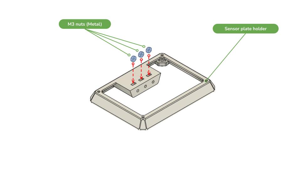
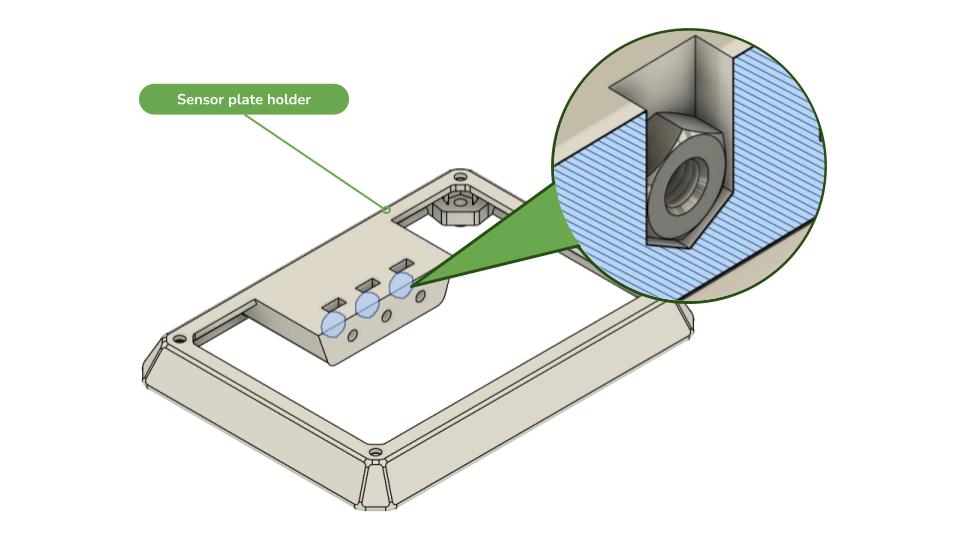
Take the 3D-printed sensor plate holder. Insert the three M3 nuts into the three recessed holes.
Make sure the nuts are fully seated and correctly oriented.
Step 6 – Attach the Sensor Plate to the Holder
Steps
Images
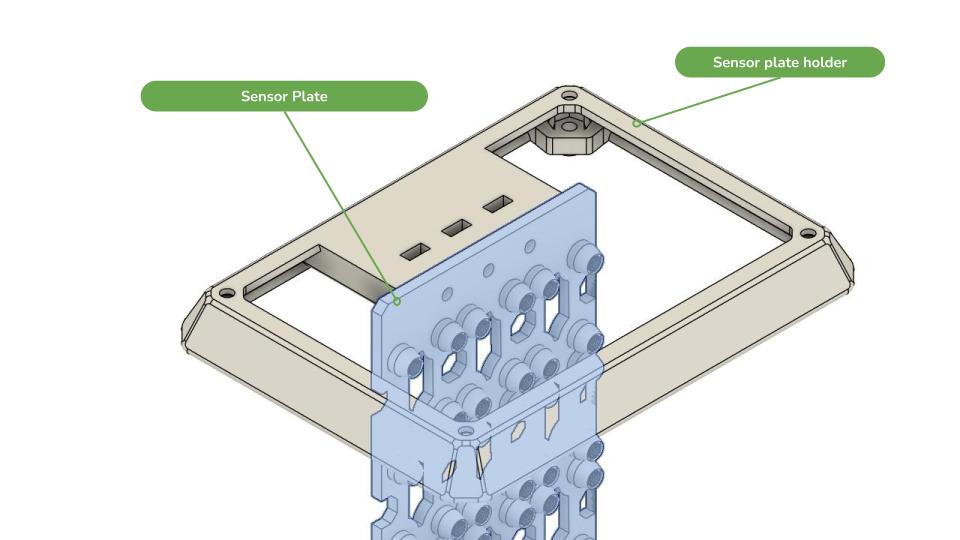
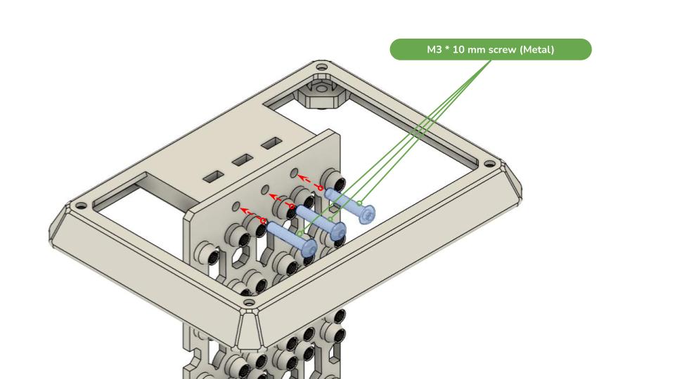
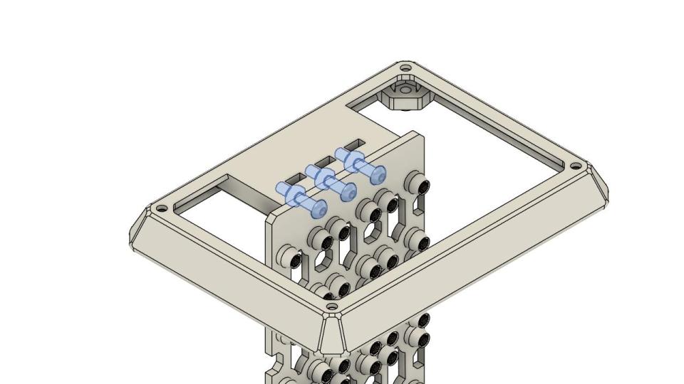
Take the sensor plate with the sensors already installed and wired. Align it with the three sensor plate holder holes.
Secure the two parts using three M3 × 10 mm screws.
Make sure the sensor plate is firmly attached and that none of the parts are loose.
Step 7 – Install the Sensor Assembly on the Stevenson Screen Top
Steps
Images
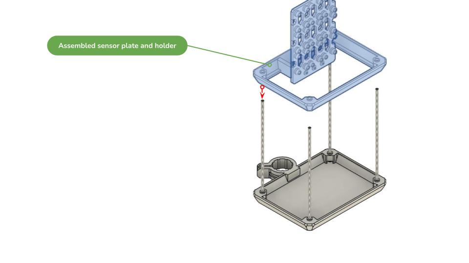
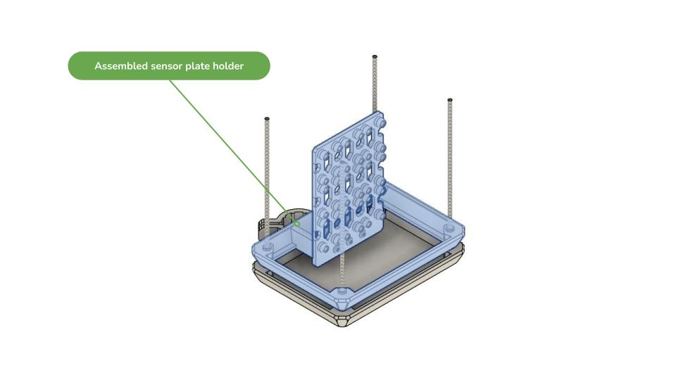
Take the assembled sensor plate + sensor plate holder. Align the four holes with the four 140 mm threaded rods installed on the Stevenson Screen top. Carefully slide the sensor assembly down over the four rods. ⚠️ Important: Lower the assembly gradually and evenly. Do not force one side down while leaving the other side high, as this can bend the threaded rods and make assembly difficult.
Push the assembly down gently until it reaches its intended position. Verify that everything is correctly aligned and securely assembled.
Step 8 – Install the Stevenson Screen Middle Sections
Steps
Images
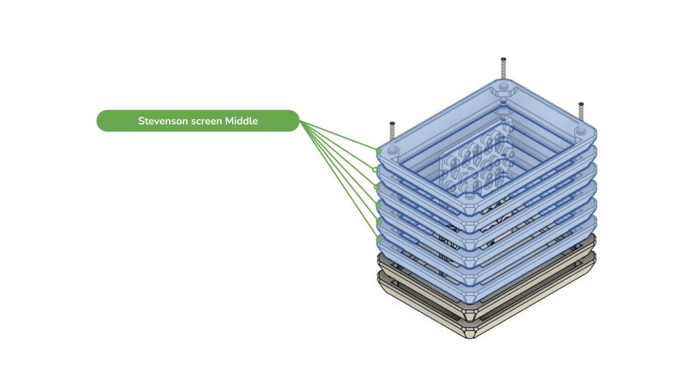
Take the six 3D-printed Stevenson Screen middle sections.Stack them one by one on top of the previously assembled components. Make sure each section is correctly aligned before adding the next one.
Step 9 – Install the Stevenson Screen Base
Steps
Images
TTake the Stevenson Screen base. Place it on top of the assembled middle sections. Check that all components are correctly aligned and that the sensor cables remain properly routed.
Step 10 – Install the Bottom Cover
Steps
Images
Take the Stevenson Screen bottom cover and place it on the base. Make sure that the cable opening is positioned on the same side as the mounting bracket. This orientation will make it easier to route the sensor cables toward the main protection box.
Step 11 – Secure the Assembly
Before securing the final assembly, verify that:
All sensors are installed;
All sensors are properly wired;
All cables are correctly routed;
The Stevenson Screen sections are properly aligned;
The threaded rods are straight;
Nothing is interfering with the sensors.
Steps
Images
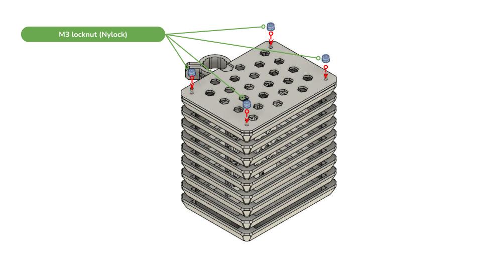
Secure the complete assembly using M3 lock nuts (nyloc nuts).⚠️ Recommended: Use nyloc nuts rather than standard M3 nuts. A regular nut can gradually loosen due to vibration, especially in outdoor installations. Once all four lock nuts are tightened, check the complete assembly one final time.
Final Check
The Stevenson Screen is now ready to be connected to the Minodu Local Network protection box and mounted for outdoor deployment.
Ensure that the sensors have sufficient exposure to the surrounding air and that the Stevenson Screen provides adequate protection from direct environmental exposure while allowing appropriate airflow.